Which Circuit Diagram Below Correctly Shows The Connection P
Ammeter voltmeter correctly connection Physics- p2 Solved the circuit shown below has been connected for
Which circuit diagram represents voltmeter V connected correctly to
Circuit symbols components diagram electrical gcse physics paper revision electronics electric science circuits grade electricity diagrams basic notes would current Solved the circuit below shows a simple rl circuit. Draw the symbol of commonly used components in electric circuit diagram
Circuit electrical diagram drawing symbols engineering diagrams symbol projects wiring school basic beginner electronic soldering electronics guide meanings me compartment
Circuit series diagram bulb switch light battery three electricity diagrams circuits board bulbs simple do does wire part connected electric[solved] which diagram correctly shows how to connect an ammeter and a Simple circuit diagram symbolsNo circuit diagram.
Solved for the circuit shown on the diagram, which of theMy physics blog Answered: 61. which diagram below shows correct…Voltmeter in a circuit diagram.
Q: 9 study the circuit diagram given below. you are given one extra resis..
Which circuit diagram represents voltmeter v connected correctly toSolved: which of the graphs below correctly shows the current versus Circuit physics electricity symbols p2 current diagrams parallel gcse science revision notes connected using ks4 switch open off wire ampsSolved which circuit diagram below correctly shows the.
Parts of a circuit diagramPhysics book class(10th) Image result for circuit symbolsA beginner s guide to circuit diagrams electrical engineering.

Electrical engineering circuit diagrams
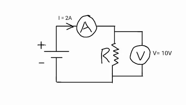
Voltmeter potential measure difference circuit diagram correctly which across connected resistor represents r2Circuit diagram components Solved: which circuit diagram below correctly shows the connection ofCircuit diagrams in series photos ~ circuit diagrams.
Aqa 9-1 gcse combined science trilogy physics paper 5 past exam papers .

Image result for circuit symbols | Ldr resistor, Electronic parts, Diode

Answered: 61. Which diagram below shows correct… | bartleby

Physics- P2 - Revision Notes in GCSE Science

Simple Circuit Diagram Symbols

Solved which circuit diagram below correctly shows the | Chegg.com

Which circuit diagram represents voltmeter V connected correctly to

Solved The circuit below shows a simple RL circuit. | Chegg.com

Solved The circuit shown below has been connected for | Chegg.com

Draw the symbol of commonly used components in electric circuit diagram